Saturday 15 August 2020

Quick Fix - Passat B6 Headlight Washer System

The Passat B6 Headlight Washer System.


1 - The Problem

A friend recently picked up a 2007 B6 Variant at a knockdown price due to a few issues, some disclosed by the seller and some not. It came with factory bi-xenons - nice - but we discovered the washer system, required by law for higher-powered xenon-equipped cars in the UK, wasn't working.


2 - The Diagnosis

First thing to check on any xenon-equipped car is whether it actually has a headlight washer system fitted, cars fitted with 20W xenons aren't required to have headlight washers but those with 30W xenons - like this B6 - are. If in doubt look at your washer bottle, if it has a hose that's considerably larger than a regular washer hose line then it's a high-pressure line designed to first pressurise and open up the rams that the jets are fitted to. I've seen numerous forum threads where owners presumed washers were fitted and proceeded to "enable" them using VCDS, only to be confronted with an error code and of course non-functional headlight washers. Just like the idea of "downloading extra memory" for your computer, enabling a feature in VCDS doesn't automatically make non-existent hardware suddenly appear.

Once you're sure you're not trying to fix a non-existent problem it's time to proceed.


2.1 - Diagnostic Check

If you have access to VCDS or other diagnostics now is a good time to run them. This was the output from our test:

00924 - Relay for Headlamp Cleaning System (J39)
            009 - Open or Short to Ground - Intermittent
             Freeze Frame:
                    Fault Status: 00101001
                    Fault Priority: 4
                    Fault Frequency: 2
                    Reset counter: 88
                    Mileage: 346164 km
                    Time Indication: 0
                    Date: 2020.08.10
                    Time: 18:47:00

             Freeze Frame:
                        OFF
                    Voltage: 12.00 V
                        OFF
                        ON
                        OFF
                        OFF
                        OFF

This essentially tells us what we already know - that there's a fault. The "open or short to ground" isn't very helpful in this case, other than identifying an electrical issue. The only realistic non-electrical failure would be a water leak preventing the required pressure to build for the washer to activate, and such a leak would be obvious to say the least.

Here's the relevant circuit...

Here we can see it's a simple system. SC35 is the protection fuse, J39 is the relay and V11 is the washer pump. The fuse provides the +12V supply to the relay switch and coil. The J39 coil finds its path to ground via the Central Electrics Control Module rather than being switched on the positive side and being directly grounded. Pump V11 receives its +12V from the J39 switch and is directly grounded via a return wire.


2.2 - Fuse Check

First check the condition of fuse SC35, then check there is +12V present. This is located at the driver's side interior fuse box.


Note the image shows the driver's fuse box on an LHD car, RHD is the mirror image. SC35 is the fourth fuse in counting from the front of the car on the middle row of full-size fuses. It's a big lad rated at 30 amps.

If the fuse is good and +12V is present then move on to checking the relay.

Result: Ours was good.


2.3 - Relay Check

Remove the driver's storage bin on the dashboard to expose the Central Electrics Control Module.


The righthand-most relay is the engine start relay (designated "433" in this image). The J39 relay for the washers, designated "53", is immediately next to it. Conveniently, on this Passat it both relays were exactly the same type so testing by substitution is easy. Switch both relays around and if the car still starts the relay is obviously good.

Result: Ours was good.

So the fuse provides power and the relay switches as it should, we now need to check there's power at the motor.


2.4 - Pump Check

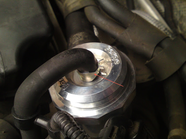
It's up to you at this point how you tackle this. The pump is visible at the front of the washer reservoir with the indicator and fog light units removed but it comes out sideways, so removing the front bumper is the officially sanctioned way of gaining access. You can gain access by removing a couple of wheel-liner screws along with the bumper-to-wing retaining screw and this will give you just enough access to remove the pump, but it will be a squeeze especially if you have massive shovel-hands. Note there is a securing clip for the high-pressure hose on the pump and an O-ring on the high-pressure output, don't lose these and ensure they're refitted when the pump is refitted or replaced.

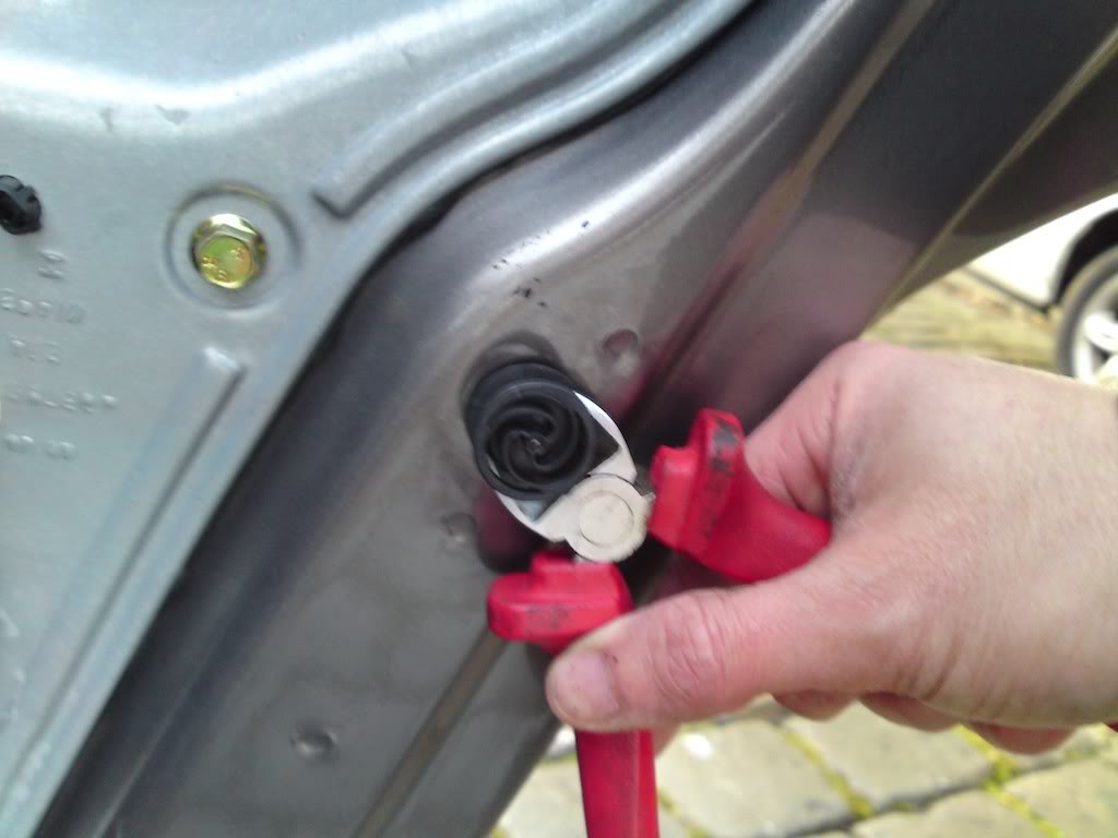
Release the latch on the pump's electrical connector, if you've not done this before first practice on an easily-accessible connector in the engine bay. Essentially you just need to insert a screwdriver into the tab at the rear of the connector, then apply pressure and push away from whatever the connector is attached to. It's easier once you know how it's done but remember some connectors won't have been released since the car was assembled and so may offer some initial resistance.

As standard, the headlight washers will activate once in every 4-5 windscreen wash cycles, and the headlights need to be switched on before the system operates. Bear this in mind when testing, if the lights aren't on you're never going to see +12V at the pump connector.

Testing is also far easier with an able-bodied assistant, for obvious reasons.

At this point, with the fuse and relay successfully tested, you should see +12V appear briefly every 4-5 operations of the windscreen wiper. If you don't then you need to start checking the wiring loom for severed wires, especially if the car has been involved in a collision.

Result: We got +12V!

Now test the pump for resistance. It shouldn't read zero otherwise the protection fuse SC35 should have blown. It's either going to read in the region of megohms, meaning it's burned out internally, or it's going to give a kilo-ohm range reading, suggesting the motor is in fact okay but it has a mechanical issue.

Result: We got kΩ!

Finally, briefly apply 12V directly to the pump. You shouldn't hear it spin up as otherwise it would work normally when fed 12V by the car, but you may hear it clunk as if it's trying to turn. Do NOT apply voltage continuously if you hear it clunk. It has a mechanical issue and continuous voltage is almost certain to destroy the motor if it can't turn.

Result: Ours clunked!


3 - The fix

Replacement with a new unit is the best option, but it's possible to revive the existing pump if you're lucky.

To do this, apply power directly from the car battery to the motor in brief pulses.

DO NOT DO THIS IF IF YOU DON'T UNDERSTAND THE POTENTIAL RISKS INVOLVED IN THE EVENT OF SHORT-CIRCUITING A CAR BATTERY. EXERCISE GREAT CAUTION AND TAKE YOUR TIME. DO NOT APPLY CONTINUOUS POWER TO THE PUMP.

We were lucky. After around fifteen pulses of full-fat 12V (actually 13.6V) directly from the battery, the motor's torque overcame whatever crap was inside the pump and it suddenly started to spin properly.

Result: RESULT!

It's luck-of-the-draw whether yours can be brought back to life in this situation, but if it's otherwise going in the bin you've got little to lose by trying it. After refitting the newly-revived pump the system pressurised properly once it had purged the air and the washers now retract correctly and it all works once more.


Thursday 26 May 2011

Seat Leon Essential Modifications - Diverter Valve Fitting Guide

All cars have their weak spots, thanks to manufacturers cutting corners to save a few pennies here and there. The 1.8 litre 20 valve turbo lump is a popular and robust unit, let down by a handful of cheaply made ancillaries.

The first of these cheap ancillary parts to be replaced has to be the diverter valve, also referred to as the dump valve.


The technical bit...

The diverter valve is vital in preventing compressor-stall when the the throttle plate is closed, due to high-pressure air getting trapped between the throttle and the compressor side of the turbo and sending a pressure wave back towards the compressor. This can cause the turbine to rapidly slow down or stall completely and puts severe stress on the compressor.

This situation can easily happen when changing gear while the turbo is under boost conditions, as most people will temporarily lift off the throttle then reapply it. If the turbo loses speed between gearchanges there will be a delay while it spins up again - better known as turbo lag.

The major problem with the standard plastic diverter valves is that they contain a diaphragm which can eventually perforate due to the high-pressure, high-temperature air they are continually exposed to. This causes a continuous loss of boost as high-pressure air is allowed to bleed away back into the intake, and this is why any enthusiast should change the original valve for a more robust unit.

Note...

Replacing the diverter valve is not strictly a performance modification and will not increase power output from standard form. The whole point is to change it for a more reliable (and serviceable) unit which will then allow the rest of the system to run as it was intended, free from any losses caused by high-pressure leaks. Having said that, if your diverter is leaking you will immediately feel the benefits from the new valve as it reclaims lost BHP.

Also note...

The alternative to a diverter valve (also referred to as a recirculating dump valve) is an atmospheric dump valve, the kind that gives that distinctive "pshhhhhhht!" sound when operating. These can cause various problems for the engine management system due to the fact that the ECU has measured the incoming volume/mass of air and calculates the amount of fuel to inject based on this. If air is suddenly removed by venting the excess out of the system, the engine will suddenly have a fuel-rich mixture which can trigger engine management warning lights and limp-home mode to kick in.

For a simple life, stick to the original diverter type valve.


What you will need...

A replacement diverter valve (obviously) - the Forge Motorsport DV007 is the valve of choice for many as it fits very well, is well made, is serviceable and has the backup of a company renowned for its excellent after-sales support. Another popular choice is the Bailey DV30.

A flat-head screwdriver, 4-5mm across.

A large cross-head screwdriver.

Jubilee clips, 2 large (genuine Jubilee "1A" types are ideal at 22-30mm range).

Either a small Jubilee clip (10-15mm range) or a fuel-hose type spring clip (Mikalor 14mm is perfect fit).

Long-nose pliers if you go for the spring clip option.


Step 1. Remove the main engine cover. Use the large cross-head screwdriver to turn the cover retaining clips (arrowed) through 90 degrees then lift the cover away and put it safe.


Step 2. Remove the original diverter valve. The valve is located near the air filter box (replacement valve fitted in the image for clarity)...


And here's the original item in all its glory...


Here's where you need the smaller flat-head screwdriver. Insert it into the single-use clips (arrowed) and keep turning the screwdriver until the clips have enough slack so they can be moved out of the way...


Once the clips are slackened pull the old valve out and put the new valve in, using the large Jubilee clips on the inlet and outlet. It will end up like this...


Here's where I chose to use the spring clip (fuel hose type) rather than a Jubilee clip (arrowed below). Access is a bit tight for even the smallest Jubilee clips and the spring clip looks fairly "factory original", not that anyone will ever know if you refit the engine cover...


Now you see it...


And now you don't...


Conclusion...

Replacing the diverter valve is an easy job and is a must for any enthusiast. My old valve definitely was leaking boost, which could be heard when the driver's windows was down. The turbo would spool up, hit a certain pitch and then drop down to a lower pitch. With the new valve the turbo hits a certain pitch and stays there. The midrange feels stronger and more flexible as a result, and the upgrade is money very well spent. Finally the replacement valve is just that, a high quality replacement and not a performance enhancing modification. With this in mind you needn't feel too guilty about not declaring it to your insurance company should you happen to forget...

DubSteve

Tuesday 10 May 2011

Seat Leon Leaking Door Seals Repair Guide

Leaking SEAT Leon 1M and Toledo doors? Welcome to the club. If there's a problem with wet carpets it's usually because of the VAG group's decision to seal the door inner carrier (which holds the window mechanism, locks, speakers etc.) with a foam strip. These foam strips eventually break down near the speakers and allow water to run inside. A few cars were recalled but most will suffer this issue eventually. VAG changed over to butyl rubber sealant as a result of this, and it's this that we'll be resealing the doors with.

There are two ways of tackling the problem, one is bodging it and the other is doing it properly which only takes a little longer. Here's how to do it properly. Overall the job is very easy and will take maybe 1/2 an hour per door, less time once you know how it's done.


Before you even think about tackling this, get onto eBay and buy the following items.

1. Search for "pry tools", the iPod/mobile/laptop opening variety. Buy some that look like this...


2. Buy some "Golf trim clips", there is every chance you will bust a couple unless you are very lucky. These are the ones you need...


3. Search for "butyl sealant strip". I bought the 6mm round stuff - 8m roll, enough for all four doors, and not too thick to be a problem when reassembling the door's inner carrier. Cheaper than the VAG branded stuff at £7.49, delivered. Looks like...


Once the postman's delivered your bits, get the following tools together. Large Philips screwdriver, T20 Torx, sharp knife, plastic pry tool, and a 10mm socket. A flat-head screwdriver and a pair of wire cutters may also come in very handy...


While the job can be done solo an able-bodied assistant will make certain tasks much easier. Assistance while disconnecting/reconnecting the door-card electrics is highly recommended. Having someone around to hold the roll of butyl sealant while you feed it in will also be a huge help.


Step 1. Remove the grab-handle cover. This is why you bought the pry tools! While you could just use a screwdriver instead of the pry tools you will most likely chew up the handle plastic while trying to pop the cover off. The pry tools do the job without totally knackering the cover. Start at the lowest point of the handle (upper side) with the pry tool and wiggle it until you have about 1mm of gap. Repeat on the lower side, then back to the upper and keep wiggling until the cover pops free...


Pull the trim from the lowest point...


And finally pull on the opener so you can get the handle cover off...


Step 2. Remove the door card. Before proceeding, wind the window down all the way. The front door has 2x T20 Torx screws at the bottom which need removing (none on the rear doors). The grab-handles are secured by two large Philips screws (arrowed)...


Now pull on the door card from the bottom. If you do it slowly and firmly then trim retaining clip casualties should be kept to a minimum. Once all the clips have popped free you will be able to lift the card slightly and move it clear of the door frame. Have an assistant hold the card while you disconnect the various wire connectors. All the connectors have one or two squeezy retaining clips. Don't be hasty and you'll have them off in no time. The door opener is fairly simply to unhook - pull on the cable outer, away from the handle, and lift it over the plastic bracket. Once you have all connectors off you should see this...


Step 3. Loosen the carrier plate. Take your 10mm socket and remove all the 10mm bolts except the two that are arrowed below. These two remaining bolts should be wound out nearly all the way, allowing you good access to the rear of the carrier without completely removing it. You could remove these last two bolts but your assistant would then have to hold the carrier while you fit the sealant strip - but you really need your assistant to hold the roll of sealant so leave the bolts in position...

Front door...


Rear door...


Now you need to break any seal between the door frame and the carrier. The best way to do this is with the large flat-head screwdriver you hopefully have ready, resting on a towel so you don't kill any paint...


Here's where my seals disintegrated, seem to be very common failure areas. Affected areas are between the arrows...

Front door...


Rear door...


Now the carrier is loosened, get to work on that seal and show SEAT how it should have been done in the first place! Start wherever you like and pull the old seal off slowly. I made an exception on the rear doors as I couldn't get as much clearance behind the carrier as I wanted and so left some of the seal in place. The next step will show what I left in place. It's adhesive backed but will come off cleanly if you are lucky. I wasn't, and was left with a few inches-worth of rotten seal on each door that had to be scraped off. I used my trusty T20 to get into the channel where the worst of the remaining rotten seal (and brown gunk) was hiding. You don't need to get the surfaces surgically clean but they do need to be dry and free of as much of the old seal and gunk as possible.


Step 4. Fitting the new seal. See the pics below. I started where I did on the front door (arrowed) due to the electric window wiring loom getting in the way. It seemed like a good starting point and worked well for me. Slowly feed the butyl sealant strip into where the old seal lived.

Front door...


As mentioned in step 3 I didn't replace the whole seal on the rear doors due to access. Here's what I did replace...


Step 4. Put it all back together. Self explanatory really. Replace any trim retaining clips that broke. Here's where I used the wire cutters to grip and wiggle free any snapped clips or clips that came off the door cards and could be reused…


And after all that, only one bust clip per door. Not bad going!


Once you've done one side the other will be a piece of cake. I'd read many online guides of varying complexity and clarity but still wasn't sure how difficult it was really going to be. Some guides suggested a need to remove windows glass or the carrier plate itself, but it's really not necessary. As it is, the job isn't difficult at all. All four doors can easily be done in an afternoon once you have everything prepared. One final note about the butyl sealant strip, it's pretty sticky stuff (even more so when warm) and it's much easier to handle when it's cold. For anybody reading this in the summer, stick your sealant in the fridge before you need it.

Main dealers will charge hundreds to replace all four door carrier seals. Following these steps my Leon is now bone dry, all for under a tenner :)

Footnote: nine years later on and my doors are all still water-tight. Follow this guide and yours will be too :)